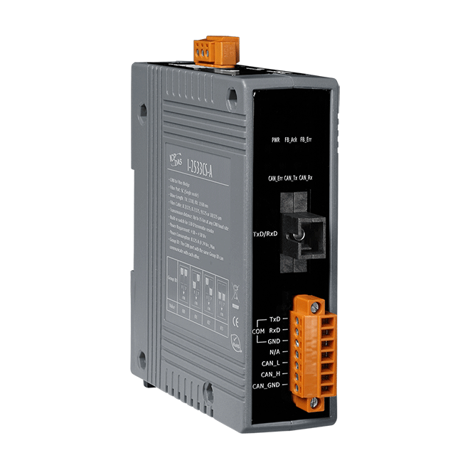
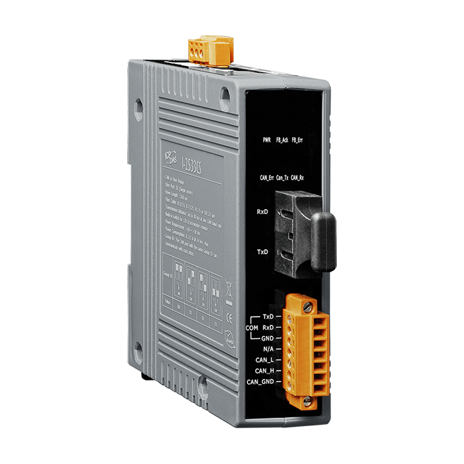
I-2533CS-A
CAN to Single-mode Fiber Bridge
Features
- Fiber Type: SC ; Single mode ; 100 Base-FX
- Maximum transmission distance up to 15km at any CAN baud rate
- NXP TJA1042 CAN transceiver
- 2500 Vrms isolation on the CAN side
- Supports both CAN 2.0A and CAN 2.0B
- Fully compatible with the ISO 11898-2 standard
- Rotary switch for CAN baud rate configuration
- Build-in switch for 120 Ω terminal resistor
- Removable terminal block, Mount easily on DIN-Rail
- Allows user-defined CAN baud rate
- Fiber broken line detection
- Utility tool for CAN message filter configuration
- The CAN port with the same Group ID can communicate with each other
Introduction
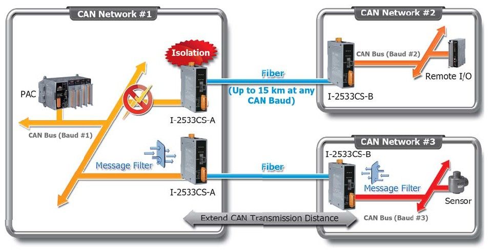
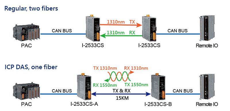
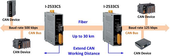
The I-2533CS-A and I-2533CS-B are local CAN bridges used to establish a connection between two CAN bus system via single mode fiber optic transmission medium. In order to solve the problem between CAN and fiber transmission medium, the I-2533CS-A/B are specially designed for converting the electrical CAN bus signal to fiber optic cables. The I-2533CS-A/B supports Wavelength Division Multiplexing (WDM) technology so that only a single fiber cable is needed for transmitting bi-directional CAN data. As the I-2533CS-A and I-2533CS-B must be paired because of hardware limitations, this means that the cost of deploying fiber cable can be effectively reduced. I-2533CS-A/B have three more important features. First, the transmission distance limitation of the CAN bus system will not affected due to the different CAN baud rate. It means that the total CAN bus working distance can be extended. Second, the bus error on one CAN network will not affect the operation of another CAN network. Finally, the two CAN network can communication with each other by using different CAN baud rate for highly flexibility.
Important Note: You must purchase both I-2533CS-A and I-2533CS-B since these products work as a pair.
Applications
Ordering Information
| PRODUCT SERIES | DESCRIPTION | QNT. | INQUIRY |
|---|---|---|---|
Similar Products
| LED Indicators | |
|---|---|
| Status | 1 x Power 3 x CAN status 2 x Fiber status |
| COM Ports | |
|---|---|
| Ports | 1 x RS-232 (Utility Port) |
| Fiber | |
|---|---|
| Ports | Single-Mode; SC connector x 1; 100 Base-FX |
| Fiber Cable | 8.3/125, 8.7/125, 9/125 or 10/125 μm |
| Wavelength | TX: 1310, RX: 1550 nm |
| TX Output | -14 dBm Min. , -8 dBm Max. |
| Transmission Distance | 15 km (9/125 μm recommended) |
| RX Sensitivity | -31 dBm Max. |
| RX Overload | -5 dBm Max. |
| Budget | 17 dBm |
| Propagation Delay | 190 us (*Note2) |
| CAN | |
|---|---|
| Ports | 1 |
| Baud Rate | 10 k ~ 1 M bps |
| Isolation | 500 Vrms on the CAN side |
| Terminal Resistor | Switch for 120Ω terminal resistor |
| Specification | ISO 11898-2, CAN 2.0A and CAN 2.0B |
| Filter | Yes |
| Power | |
|---|---|
| Input Range | +10 VDC ~ +30 VDC |
| Consumption | 3 W |
| Mechanical | |
|---|---|
| Casing | Plastic |
| Dimensions (mm) | 33.0 x 126 x 101 (W x L x H) |
| Installation | DIN-Rail |
| Environment | |
|---|---|
| Operating Temperature | -25 ~ +75 °C |
| Storage Temperature | -30 ~ +80 °C |
| Humidity | 10 ~ 90% RH, Non-condensing |
Specification Memo
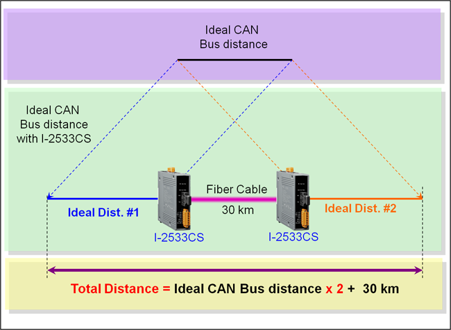
Note2: The propagation delay depends on the CAN Bus baud rate and the CAN message format. This value has been tested using a CAN baud rate of 1 Mbps, the CAN ID 0x12345678 and 8 bytes of data with a value of 0xFF.

| CAN Baud rate [bit/sec] | Ideal Fiber Length [km] |
|---|---|
| 1M | 30 |
| 800K | 30 |
| 500K | 30 |
| 250K | 30 |
| 125K | 30 |
| 50K | 30 |
| 20K | 30 |
| 10K | 30 |